
Complete Complete Week 6 and 5 for DC Circuit Course Assignment
ABSOLUTELY NO COPYING FROM ANOTHER SITE OR SOURCE…MUST SHOW WORK IN MICROSOFT WORD DOCUMENT…PLEASE SEPARATE EACH ASSIGNMENT…NEED A DC EXPERT
WEEK 6
RC and L/R Circuits
- Consider the series L/R circuit below:
- What is the time constant of the circuit with S1 closed?
- What is the eventual steady-state current with S1 closed?
- What is the value of the circuit current at the first instant S1 is closed? (t = 0s)
- What is the value of the circuit current exactly one time constant after S1 is closed?
- How long after S1 closes will it take before the circuit current reaches its steady-state value?
- For the same circuit, assume that the switch S1 has been closed for more than five L/R time constants. If a 1MΩ resistor is placed across the terminals of the switch, calculate:
- The approximate time constant of the circuit with S1 open.
- The peak inductor voltage VL, when S1 is opened.
- The di/dt value the instant S1 is opened.
- How long it takes for the current to decay to zero after S1 is opened (approximately).
Series L/R Circuit: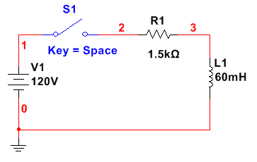
- Consider the series RC circuit below:
- Assume C1 is completely discharged with S1 in the position shown. If S1 is moved to the top position, how long will it take for the capacitor voltage to reach
- 3V
- 6V
- 15V
- 20V
- Assume that C is completely discharged with S1 in the position shown. If S1 is moved to the top position, how much is the resistor voltage at the following time intervals?
- t = 0 s
- t = 4.5 ms
- t = 10 ms
- t = 15 ms
- t = 25 ms
- Assume that C is fully charged with S1 in the top position. If S1 is moved to the bottom position (as shown), how long with it take the capacitor to discharge to:
- 4 V
- 8 V
- 12 V
- 18 V
Series RC Circuit: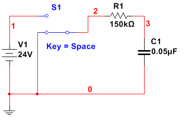
- What is the time constant of the circuit with S1 closed?
- What is the eventual steady-state current with S1 closed?
- What is the value of the circuit current at the first instant S1 is closed? (t = 0s)
- What is the value of the circuit current exactly one time constant after S1 is closed?
- How long after S1 closes will it take before the circuit current reaches its steady-state value?
- The approximate time constant of the circuit with S1 open.
- The peak inductor voltage VL, when S1 is opened.
- The di/dt value the instant S1 is opened.
- How long it takes for the current to decay to zero after S1 is opened (approximately).
Series L/R Circuit:
- Assume C1 is completely discharged with S1 in the position shown. If S1 is moved to the top position, how long will it take for the capacitor voltage to reach
- 3V
- 6V
- 15V
- 20V
- Assume that C is completely discharged with S1 in the position shown. If S1 is moved to the top position, how much is the resistor voltage at the following time intervals?
- t = 0 s
- t = 4.5 ms
- t = 10 ms
- t = 15 ms
- t = 25 ms
- Assume that C is fully charged with S1 in the top position. If S1 is moved to the bottom position (as shown), how long with it take the capacitor to discharge to:
- 4 V
- 8 V
- 12 V
- 18 V
Series RC Circuit:
WEEK 5
Series and Parallel Inductive Reactance
- Consider the series inductive reactive circuit:
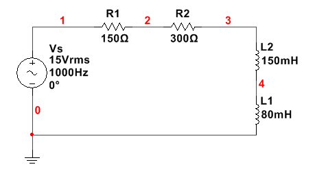 Calculate the following: (Express all answers in magnitude/phase angle form)
- Zeq
- IT
- XL2
- XL1
- VR1
- VR2
- VL1
- VL2
- Consider the parallel inductive reactive circuit:
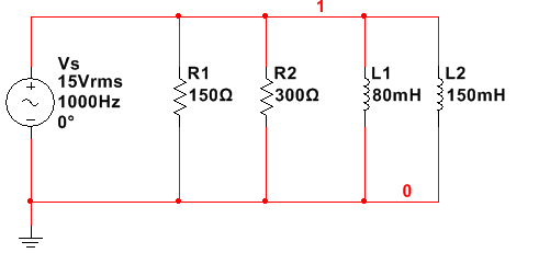 Calculate the following: (Express all answers in magnitude/phase angle form)
- Zeq
- IT
- XL2
- XL1
- IR1
- IR2
- IL1
- IL2
Do you need a similar assignment done for you from scratch? We have qualified writers to help you. We assure you an A+ quality paper that is free from plagiarism. Order now for an Amazing Discount!
Use Discount Code "Newclient" for a 15% Discount!
NB: We do not resell papers. Upon ordering, we do an original paper exclusively for you.

